Technical information
There are a number of sources for technical information on the early M24 Gold Stars, Including the BSA Service Sheets which are listed below. There is also the BSA WDM20 website http://wwww.wdbsa.nl which has an excellent technical section. Although the website is concerned primarily with the BSA Military M20 side valve machines, many of the engine, gearbox and cycle parts were shared with other BSA machines including the M24 Gold Star.
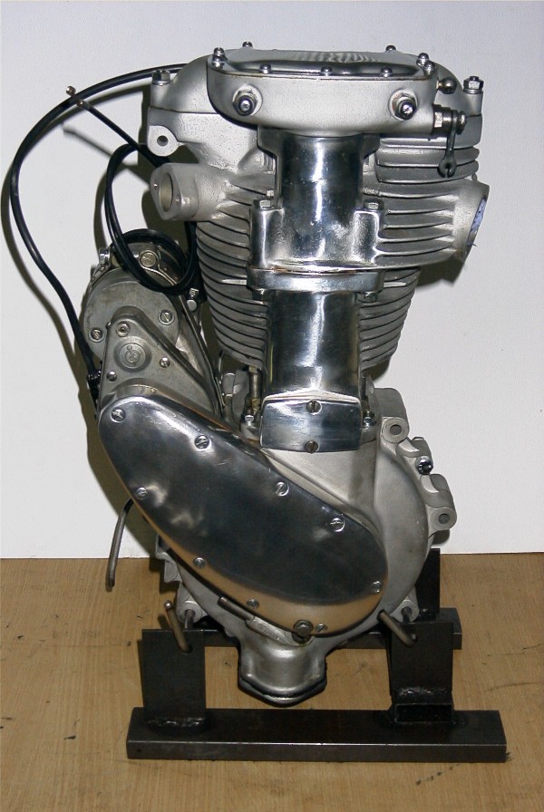
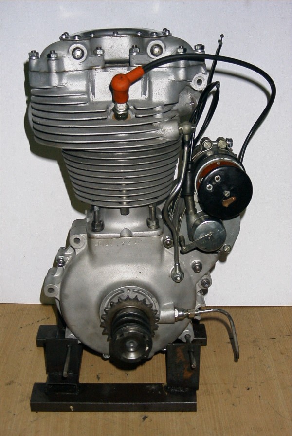
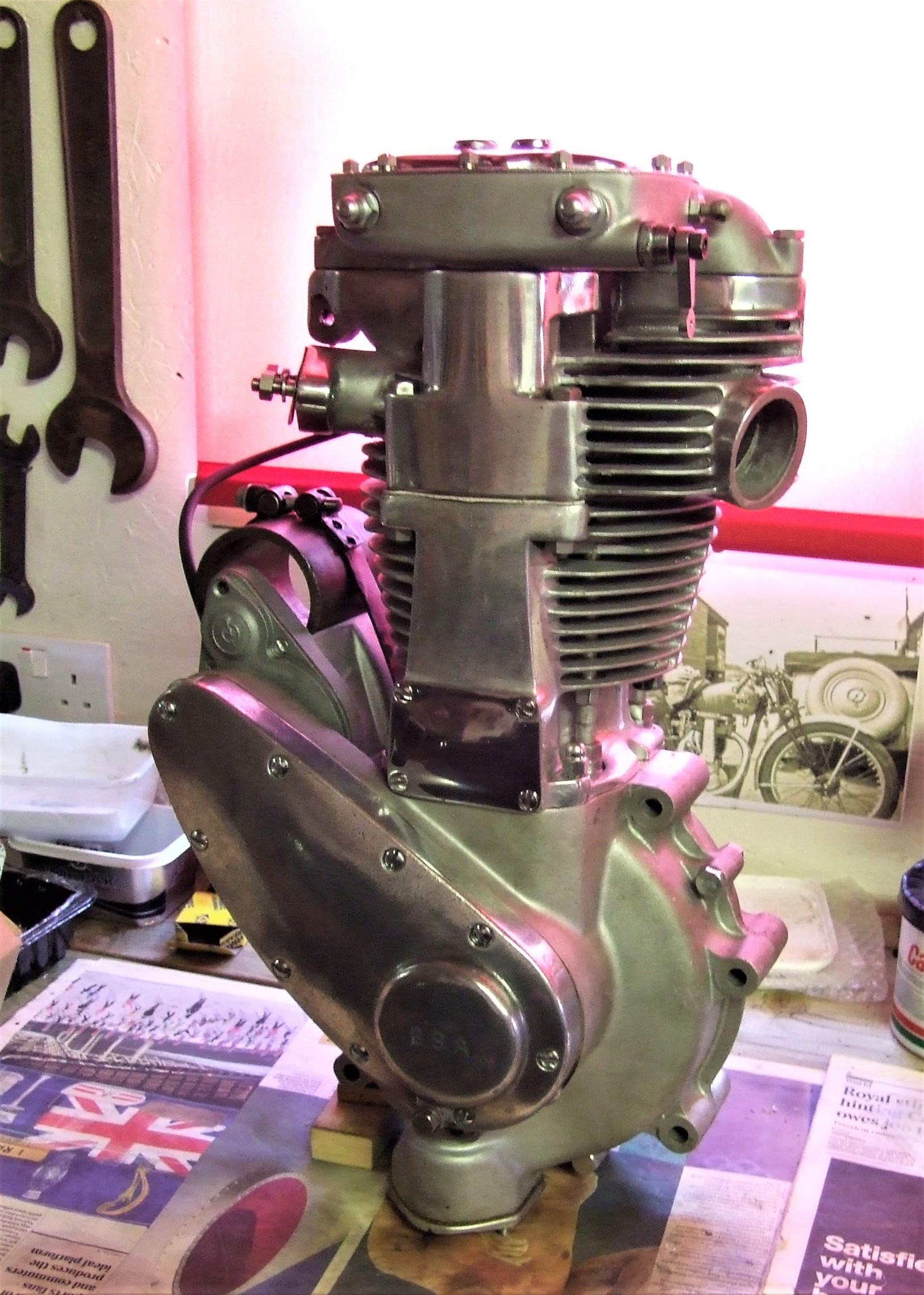
1938 BSA JM24 Engine
2. M24 Cams
3. Colour scheme
4. Electrical equipment
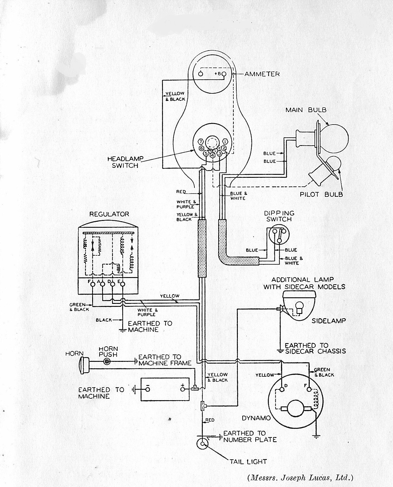
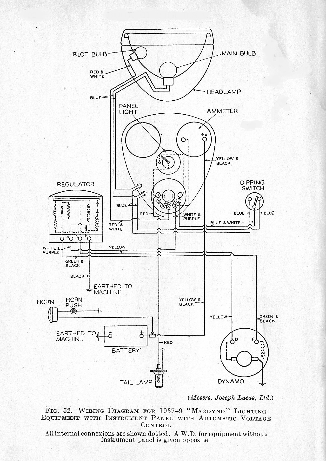
5. Wiring diagrams
6. Gold Star Screw threads
7. Gearbox and Sprockets number of teeth
8. Transfers
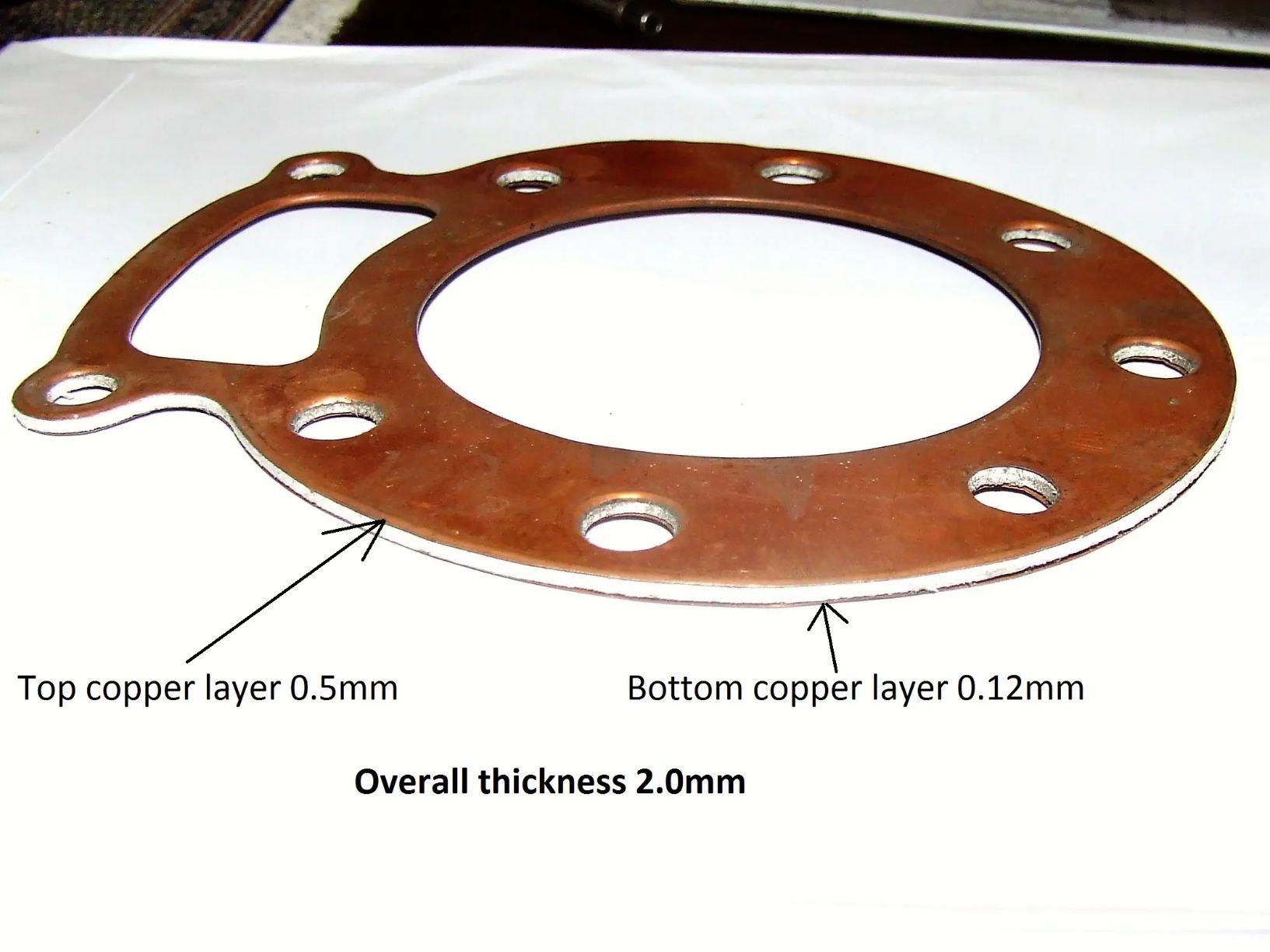
9. Gaskets
10. Bearings
11. Bush and shaft diameters (service sheet No. 702)
12. Mudguards and stays
13. Crankshaft balance factor.
14. 'Sensible' improvements (the BSA clutch)
15. Better braking
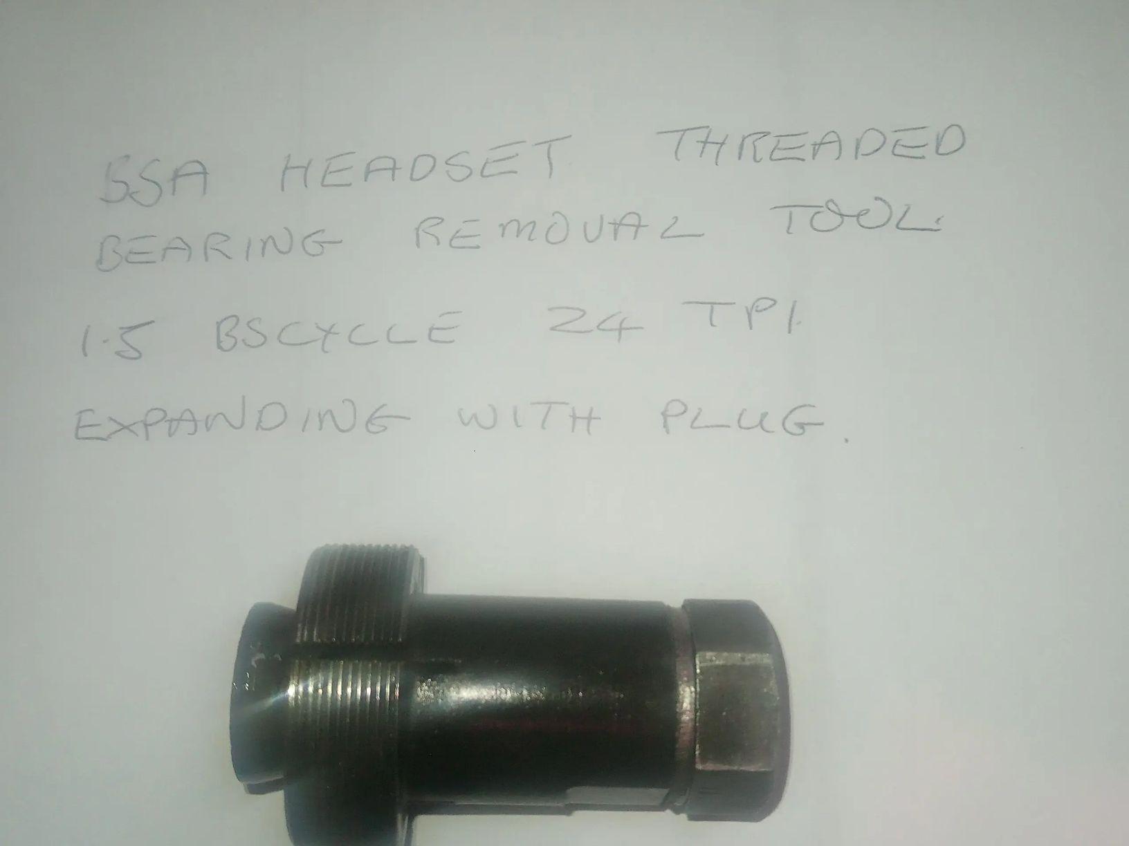
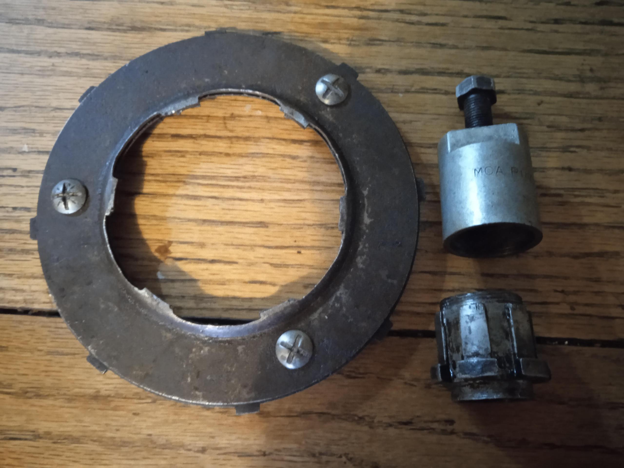
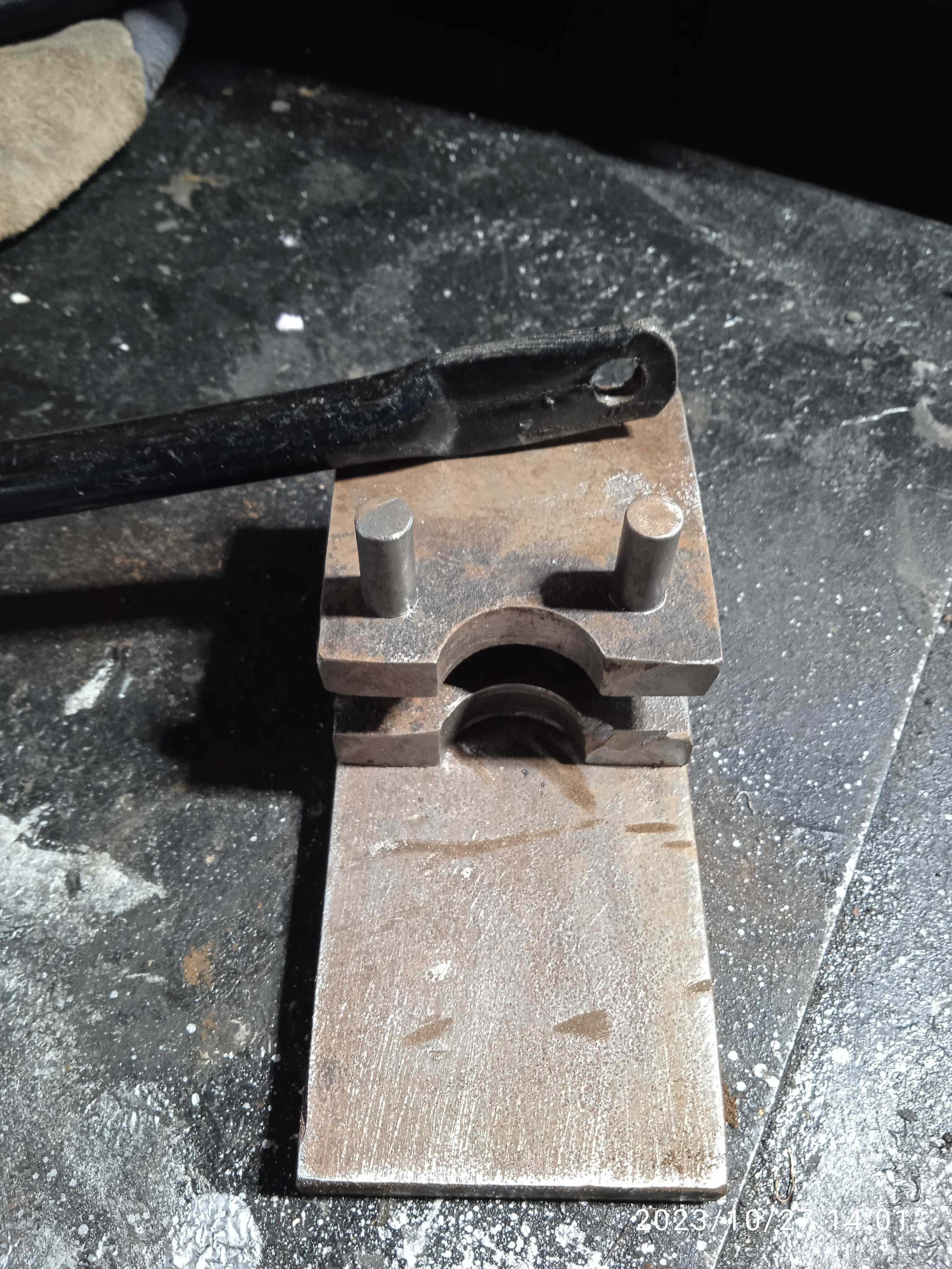
16. BSA workshop tools
17. BSA Service sheets
KM24 engine 1939
| 1) GENERAL DATA Engine: Single port, 496cc OHV single cylinder. Bore 82mm, Stroke 94mm. Compression ratio 7.75:1 (Option of 12.5:1 with High Compression Piston) Power output 29-30bhp @ 5,800rpm Alloy cylinder head with cast-in bronze thread inserts, and screwed-in steel valve seats. Alloy cylinder barrel with pressed-in steel liner Valves: Inlet: length 4.21875in Head Dia 1.65625in Stem Dia 0.34375in Exhaust: length 4.21875in Head Dia 1.59375in Stem Dia 0.375in Valve timing degrees: JM24 KM24 Inlet opens (before TDC) 35 (66-2082) 25 (65-2420) Inlet closes (after BDC) 75 65 Exhaust opens (before BDC) ? (66-2084 65 (65-2420) Exhaust close (after TDC) ? 25 Ignition: Lucas MO1 Magdyno with manual advance. Ignition timing 7/16in (11mm) BTDC on full advance
|
Fixings
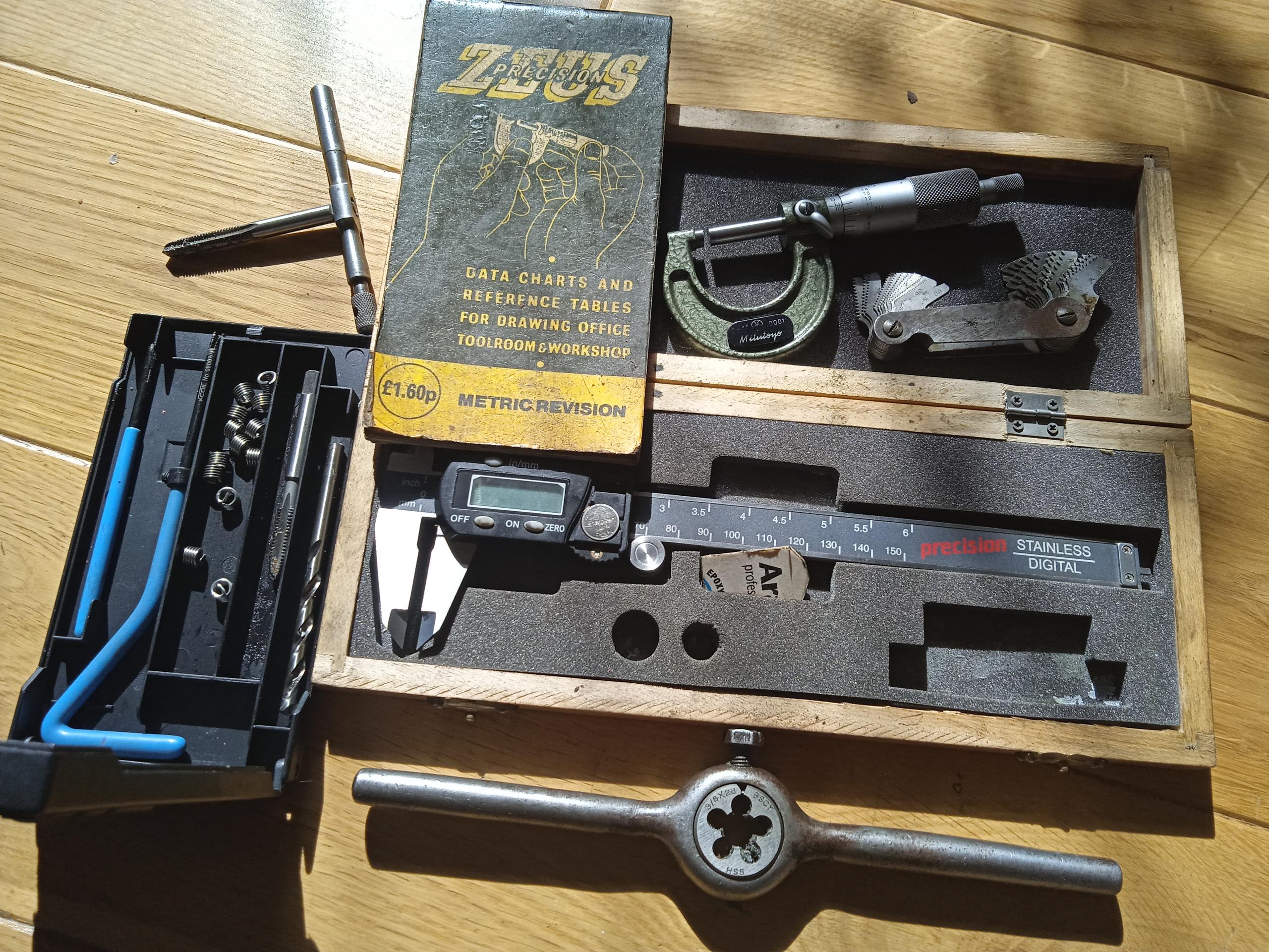
6) GOLD STAR SCREW THREADS Reproduced below is an article by Jon Luke, Technical Officer from the GSOC Gold Star Owners Club. It has been adapted from Jon's work, which focused primarily on the later 1950's and 60's Goldies. The majority of threads on all Gold Stars (pre and post war) are BSC or 'Cycle' thread, with BSW or 'Whitworth' used on odd larger threads and stud fixings into aluminium engine and gearbox casings. Lucas electrical equipment and some handlebar fixings use smaller BA 'British Association' threads. Many threads and fixings are found on the later Gold Stars and a later parts book or the excellent BMS 'The Gold Star book' can be useful when checking part numbers. It is common to find evidence of repairs made with what ever was available at the time. It is however better to repair or restore an original un modified bike, with the correct threads and fixings. Jon says it is worth investing in some measuring equipment and also taps and dies for the more common sizes, so studs, nuts and bolts can be repaired or remade. Stainless steel thread repair insert kits can be bought which provide a way or repairing threads in aluminium casings, and as an alternative to welding up the damaged thread hole and re-tapping to the correct size.
GOLD STAR SCREW THREADS – A GUIDE
Many have asked the question ‘How many different threads can you have on one motorbike’, and there does
seem to be ongoing confusion on this point. All the threads on a Goldie are the old imperial types to the
British Standards of the day. Given that the
imperial threads have been out of production for 60+ years now, very few of us are now left who used and
understood them in the day. This article is a guide to understanding and identifying the threads on your
Goldie so that you can deal with them accordingly, even down to ordering the right taps and dies for repairs. British Standard Cycle (BSC) or just ( Cycle) is a fine thread, these are sometimes known as Cycle
Engineers Institute threads (CEI). This thread form is very common on Goldies and covers the great
majority of the threads found. This thread will be found in all diameters from 3/16 inch upwards, and it comes in two pitches namely fine at 26 TPI and course at 20 TPI,
simple as that! All the large threads such as the clutch nut, crank shock
adsorber nut, wheel spindle threads etc, etc, will be BSC cycle in either 26 or 20 TPI pitches, this includes
certain light alloy threads such as the telescopic head bolts into the crankcase. British Standard Whitworth (BSW) is a course thread and most suited to soft materials and is used on Goldies for pretty much all the threads cut into light alloy parts. Imperial thread pitch is measured in ‘threads per inch’ and diameter in inch fractions, so in light alloy parts expect BSW threads in the following sizes and pitches, 3/16 x 24, ¼ x 20, 5/16 x 18, 3/8 x 16, 7/16 x 14. The next series of threads that you will encounter are BA (British Association) threads which are used on smaller components and come in 11 sizes. where 0BA is the largest at about 6mm diameter down to 10 BA which is tiny and will only be found inside fine instruments such as the speedo and the ammeter. On a Goldie they are almost exclusively used on electrical equipment although the 0BA is widely used on Amal handlebar controls and there is some BA in the carbs. British Standard Pipe threads (BSP) these are weird at first sight but make sense when explained, these will be found on some Goldie pipes notably the engine oil pipes and the fuel pipes. These threads are dimensioned around the cross bore of the hole through the thread that the fluid passes, so a ¼ BSP thread has a diameter of .518 inch and is 19 TPI, to allow a ¼ inch diameter fluid passage through the thread. In addition to the ¼ BSP mentioned, you will find 1/8 BSP on some fuel taps, this is .383 inch diameter x 28 TPI. Also on some fuel taps you will find 3/8 BSP which is .656 inch diameter x 19 TPI. Note here that fuel tap to tank adaptors may be found which are 1/4 BSP-3/8 BSP. The other specialist sector thread series to be aware of is the Model Engineers (ME) series, like BSC Cycle
these come in all fraction sizes with a 32 TPI course series and a 40 TPI fine series. The only use that I’m
aware of on a Goldie is a 40 TPI ME thread on the GP (TT) carburettor pilot fuel screw. 'The Whitworth BSW standardised thread form came complete with a standardised series of hexagon (nut) sizes. The hexagon sizes mostly found are .445 inch
across flats (AF), .525 inch AF, .600 inch AF, .710 inch AF with some bigger and smaller sizes found occasionally. The AF size relates to the bolt diameter but this relationship varies according to the thread
type. For example .525 inch AF is the correct size for ¼ inch diameter Whitworth bolts, but correct for 5/16
inch diameter BSF bolts, hence a .525 spanner is marked ¼ and 5/16 on the jaws. BSC Cycle threads follow
the BSF pattern of hexagon (nut) sizes, but there are exceptions where the next hexagon size down is used for
space and appearance reasons. Two obvious examples are the handlebar clamp bolts which are .445 inch AF instead of the .525 inch normally used for 5/16 inch thread diameters.
So there you have it, it really is as simple as that!!!!!!!.
I suppose that the obvious question here is that if all this stuff has been obsolete for 60 years, how do
we get spares and repairs done? Simple answer is that all the taps and dies in all these sizes are readily
available new and to good quality at economic prices so never really an issue once you know what you need.
Several suppliers are in the business but far and away the most comprehensive and efficient is Tracy Tools
of Torquay in Devon, see their website and speedy ordering service.
Two other useful bits of kit worth having with regards to threads are a set of thread gauges, these are like
feeler gauges except that each piece has a thread form cut in one side and is marked with the TPI number.
The gauges are offered up to the thread to be measured and a match found which tells you the TPI
accurately. The other useful item is a Zeus Precision Book of Thread tables, this is pocket sized on
plasticated paper for workshop use. A small digital caliper is also handy to get your bolt diameter right
although you will need to convert the decimal diameter to a fraction.
GOLDIE SCREWTHREAD DETAILS -AS FOLLOW: Screws and studs tapped directly into aluminium (with exceptions) are 3/16 inch x 24 TPI BSW, 1/4 inch x 20 TPI, BSW, 5/16 inch x 18 TPI BSW, 3/8 x 16 TPI BSW Engine mainshaft – cush drive nut ¾ inch x 20 TPI BSC Timing side shaft 1/2 inch x 20 TPI BSC Crank pin 7/8inch x 20 TPI BSC )Magneto pinion (extractor thread 11/16inch x 20 TPI BSC
Magneto spindle 3/8 inch x 20 BSF, Valve lifter sleeve ½ inch x 20 TPI BSC, Timing cover relief valve KM 3/8 inch x 20 TPI BSC
Crankcase - oil pipe adaptors 3/8 inch x 20 TPI BSC, Gearbox mainshaft – clutch end 5/8 inch x 20 TPI BSC
Gearbox mainshaft – selector end 9/16 inch x 20 TPI BSC Gearbox – sleeve gear 1 7/32 inch x 24 TPI BSC Gearbox selector shaft 7/16 inch x 20 TPI BSC Gearbox drain plug 7/16 inch x 20 TPI BSC
Gearbox inspection cover 3/16 inch x 24 TPI BSW, (Rear brake anchor ½ inch x 20 TPI BSC, rear wheel/brake drum spindles 9/16 inch x 20 TPI BSC, rear wheel spindle 9/16 inch x 20 TPI BSC, or rear brake spindle 7/8 inch x 20 TPI BSC, further checking of data required ) – Steering head adjusting sleeve outer 1 5/16 inch x 24 TPI BSC
Steering head adjusting sleeve – inner 1 1/8 inch x 24 TPI BSC, Touring footrest stud ½ inch x 20 TPI BSC
Fuel taps – small thread (1/8 BSP) .383 inch x 28 TPI BSP
Fuel taps larger thread, oil pipes, fuel pipes (1/4 BSP) .518 inch x 19 TPI BSP
Fuel taps very large thread, fuel tank boss (3/8 BSP) .656 inch x 19 TPI Some Amal handlebar controls 0 BA
Some Amal equipment & Lucas equipment 2 BA and 4 BA
Spark Plug 14mm x 1.25 mm pitch
TRAPS FOR THE UNWARY
Thread angle is the angle between the flanks of adjacent threads, and it varies according to thread form.
BSW, BSF and BSP have an angle of 55 degrees, while BSC threads of 26 TPI have a 60 degree angle, and
BA is 47.5 degrees. ¼ x 26 BSF and ¼ x 26 BSC are consequently not interchangeable although how to tell
a ¼ BSC from a BSF is impossible and they don’t fit together too well. The trick here is to buy ¼ BSC taps
and to just run through any new nuts before use. A further complexity is that the BSC x 20 TPI threads have
the Whitworth thread form with the 55 degree thread angle!
There is a similar problem with 0BA which is 6mm x 1mm thread pitch, while a 6mm metric coarse thread
is also 1mm pitch, these are again not interchangeable since the metric thread angle is 60 degrees. Care is
needed with Amal handlebar controls where original equipment is likely to be 0 BA, while replica parts
could be 0 BA, but more likely to be 6 x 1 mm metric coarse.
It is an inescapable fact that some manufacturers of replica parts, particularly in the far east, just might not
have read British Standard 811:1950 Revision lately. Consequently, new parts with the right thread and the
right diameter might not fit properly, I saw an instance with a replica Triumph clutch conversion securing
nut recently. The solution here is to recognise that the finer details of acceptable manufacturing tolerance
have been lost in the mists of time and that you might well need to buy the taps and dies and run the threads
through before use.
TIP The BSA 'reduced head', handlebar bar fixing bolt 5/16 BSC, can be usefully adapted with those with access to a die, and or a lathe, for several other applications such as headlamp, headlamp stays, mudguard stays and mudguard fixing bolts.
7) Gearbox and sprockets: number of teeth
Sprockets and Gearbox pinion teeth for M-Series and Post War early B Series
|
Standard M-Series JM and KM 24 |
Close Ratio KM24 |
Post War Gold Star (for information) |
Post War Gold Star (for information |
|
|
|
|
|
Engine Sprocket (16,17,18,19,20 also) |
21 |
21 |
|
|
Clutch Chainwheel |
43 |
43 |
|
|
Gearbox Sprocket (16,19 also) |
18 |
18 |
|
|
Rear Sprocket |
42 |
42 |
|
|
|
|
|
Medium close: Scrambles |
Extra close: Road racing |
Mainshaft |
|
|
|
|
1st C |
16 |
16 |
18 |
19 |
2nd C |
20 |
20 |
22 |
23 |
3rd B |
25 |
25 |
25 |
25 |
4th A |
28 |
26 |
28 |
26 |
Layshaft |
|
|
|
|
1st F |
29 |
29 |
27 |
26 |
2nd E |
25 |
25 |
23 |
22 |
3rd D |
20 |
20 |
20 |
20 |
4th D |
17 |
19 |
17 |
19 |
*Speedometer drive front hub drive ring 70T, Speedo gearbox 23T for the 20inch diameter front wheel, and 22T for the 21inch wheel which was used on the competition models.*
BM 4/24
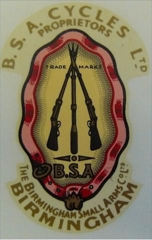
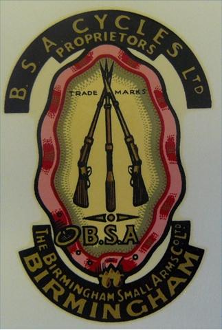
8) Transfers BSA transfers are readily available. The JM24 Gold Star had the early 'large' Gold Star transfers on the petrol tank, and a large 'piled arms' transfer on the oil tank. There was also a BSA pre 53 'garter' transfer on the headstock, the earlier one with the lighter background, The 1939 KM24 had a pre 53 garter transfer on both the oil tank and the headstock, which was the one with the darker background.
9) BSA JM24 1938 and KM34 1939 Gaskets
(Gaskets marked* are common to other M or B group machines)
Note: Pre war Gold Star ‘gaskets’ (or washers according to the parts books) which are not common to other models are now virtually unobtainable. It is worth retaining any used gaskets for a ‘pattern’ so new gaskets can be made from ‘gasket paper’ obtained from a ‘Motor factors’ or ‘auto parts store’. Copper head gaskets may be re-used, or made from sheet material which needs to be annealed before use. ‘Wellseal’ jointing compound can be used for the cylinder head to cylinder barrel joint. The fibre washers used for drain plugs can be bought from auto stores, and off the internet.
Name |
BSA Part number |
Notes |
Cylinder head ‘washer’ or gasket |
66-189 |
Copper |
Cylinder base washer |
66-192 |
Paper (B34 is similar) |
Rocker box top cover joint washer |
66-344 |
Paper |
Rocker box cover front joint washer |
66-326 |
Thick card |
Rocker box (valve chest) joint washer |
66-325(2) |
Thick card |
Timing cover joint washer * |
99-1909 |
Common to all 40/50’s M&B group machines. |
Tappet cover joint washer (JM24) |
66-1932 |
1938 |
Tappet cover joint washer(KM24)* |
66-1937 |
1939 onwards M&B Group |
Crank case scavenge (sump) cover washer* |
66-2612 (2) |
Common to all 40/50s M&B group |
Gearbox outer cover joint washer* |
66-3068 |
Common to WDM20 etc. |
Gearbox inner cover joint washer* |
66-3069 |
As above |
Gearbox inspection cover washer* |
15-4110(2) |
As above |
Mainshaft felt washer* |
24-4232 |
|
Gearbox oil filler plug washer* |
M196a |
|
Chaincase and crankcase joint washer* |
66-7575 |
As above |
Chaincase rear felt washer* |
15-8814 |
Felt |
Chaincase joint washer* |
66-7514 |
Cork |
Chaincase oil level plug washer* |
EB242 |
|
Chaincase inspection cap washer* |
27-207 |
|
BM 9/23 |
|
|
11) BSA M24 WORKSHOP DATA BEARINGS from SERVICE SHEET 703
Location |
BSA Part No. |
Hoffman No. |
Skefko No. |
Ransome & Marles No. |
British Timkin No. |
Fischer No. |
Crankcase Roller Bearing D/S |
24-724 |
R.325L |
402454.B |
MRJA.25 |
- |
MFM.25 |
Crankcase Ball Bearing D/S |
24-732 |
325 |
6305 |
MJ.25 |
- |
6305 |
Crankcase Roller Bearing G/S |
24-722 |
RM.9L |
CFM7/C2 |
MRJA7/8 |
- |
RFM.9 |
Crankpin (big end) |
See details below |
|
|
|
|
|
Gearbox ball journal |
24-4217 |
L.S.8 |
RLS.6 |
LJ3/4 |
- |
LS.8 |
Gearbox sleeve gear |
24 065 |
135 |
6207 |
LJ.35 |
- |
6207 |
Wheel bearings (taper roller) |
24-6860 |
|
2K.1178X 2K.1130X1 |
|
1178.X 1130.N1 |
|
BM 10/23
Big end bearing
66-0490 Conrod liner / big end bearing outer race
66-0545 Crank pin
66-0503 Bearing cage
24-0375 Big end rollers x 24
31-0298 Crank pin nuts x 02
65-0479 Crank pin screw
31-0300 Big end nut lock washer x 02
02-0077 Big end washer screw
66-0491 Small end bush
02-0036 Crank pin key (pre- war number EA 0101)
The reference number for the ALPHA bearings big end bearing complete is B14.
Some WD M20 models had a big end bearing with no cage.
This is known as the crowded roller type.
12) M24 Goldstar Mudguards and stays
The two model years have different
mudguards and the BSA parts books are a little
unclear in that an upright stay (to support the pillion pad area of the mudguard) is
not listed for the 1938 bike although it can be clearly seen in some pictures and
Photographs. The upright stay is listed in the 1939 Parts Book.
Description JM24 KM24 Competition Notes
Front Mudguard |
66-6529 |
66-6532 (5.5 inch) (wider with indents for fork) |
66-6555 B25 comp 65-6521 (4.5 inch) |
Competition guard has two pressed mounts for the mumber plate brackets, and the rib is also missing for the fixing area to the fork. |
Valanced type |
15-7153 |
65-6534 |
|
|
Front Mudguard stay |
66-6540 |
66-6540 |
65-6522 and B25 comp |
|
Rear Mudguard |
66-6737 |
66-6940 Valanced |
66-6872 JM 66-6950 KM 65-6787 B25 |
M24 comp similar to B25 (6 inch flat section |
Rear Mudguard Tail |
66-6739 |
66-6941 |
|
|
Upright stay |
(See notes) |
66-6945 (2) |
65-6804 |
No upright stay listed but clearly fitted on some machines to support area of the mudguard pillion pad |
Bottom stay |
66-6891 |
66-6891 |
|
(left and right) |
Lifting stay |
66-6884 |
66-6884 |
65-6805 |
M24 comp same as B25 |
Front Stand |
66-4727 |
66-4727 |
65-4693/3 |
|
Front stand for valanced type mudguard |
66-4729 |
66-4729 |
|
|
13) Sensible improvments: The BSA clutch
The BSA 6 spring clutch is prone to wear, clutch drag and slip. Sometimes all at the same time! Replace any parts which have suffered wear or from heat distortion. A popular modification has been to fit the superior Triumph/BSA 4 spring clutch with the required centre adaptor. There are two types. the mainshaft taper angle is the same, but the diameter of the taper is different. The larger diameter taper is correct when fitted to the earlier box. The swinging arm type is smaller. Care is needed to ensure correct primary chain alignment, check with a straight edge. If there is poor alignment adjustment will be needed, or there will be premature wear of the clutch basket and the sprockets. The advantage of staying with a chain primary drive, rather than a belt drive, is that it is easy to change gear ratios by swaping the engine sprocket for one with fewer, or more, teeth. It is possible to change from a four lobe to a later two lobe cush drive but for every day use the 4 lobe is just fine.
For information: An alternative clutch modification, which was popular with racers and competition riders using later gearboxes in the 50/60s, was to fit a Norton 3 spring 'Dominator' type clutch. The Norton clutch is very good (better than the 4 spring Triumph) and has an internal 'splined' centre which will fit with the early BSA A7 twin 'splined' gearbox mainshaft, if one can be found. It is a straight swap, and was marketed by Eddie Dow as a very useful modification for owners of the post war models.
14) Better Braking
The BSA M24 has a 7 inch diameter front brake, which was also used on
the BSA M20. This brake is not an efficient stopper and BSA
introduced the more efficient, single side, Gold Star 8 inch brake in
1950. Some owners have fitted the visually similar, but wider and
more efficient, brake used on the later unit singles and unit twins.
The early 7 inch brake can however, be made better for everyday
riding, by firstly bringing it back firstly to the standard factory
specification, and secondly also altering the lever action.
The standard drum brake may be improved by fitting new linings, if worn, and ensuring the brake drum is both smooth and round. Racers often have their drum brakes ‘skimmed’ on a lathe so they are perfectly round, worn brake shoes relined, but then also machined on a lathe for an optimum fit. It is best to have the drum machined when built into a wheel as the drum can distort when a wheel is built subsequently. Racing brake linings need heat to be efficient, so for every day road riding a more responsive brakes with softer linings may be preferred.
A common problem may be also wear in the brake plate housing, and the brake operating cam. This may require attention also by ‘shimming’ or machining a sleeve to size. The result should be much improved front wheel braking.
In the UK Classic Brake Services specialise in this work
Address: The Old Bank 102 Buxton Road Horwich End, High Peak SK23 7JH
Phone: 07811 356619
Set up
The M24 uses a combination of
Bowden cable and a detachable rod to operate the front brake. It is
important to use heavy duty cable to minimise the possibility of any
cable stretch when the brake is applied. For maximum leverage and
braking effect it is also important to try and position the brake
lever to set it as near as possible, to 90 degrees between the lever
and the direction of pull. There is however a problem
with the M24 brake in that the usual lever position is nearer to 45
degrees than 90 degrees! adjustment
of brake cable/brake rod length may be needed, and the curved brake
lever cam can be turned on its splines, to alter the angle it engages
with the square end of the brake cam spindle, to get the best angle
of leverage.
However
even with good set up, the brake arm angle may be far from the ideal
90 degrees at the point when the brake is applied.
Further improvements
The
brake lever can be increased in length to give more leverage (picture
1) but if looking original is less important than increased braking
efficiency, the lever can also be reversed in position to extend to
the rear and a heavy duty brake cable used, (as on the WDM20) instead
of the brake rod. An angle bracket can then be made with a cable
adjuster to position the brake cable between the front mudguard and
the front offside girder fork leg. (picture 1)
The advantage of this set up is much improve braking, but without making any alterations which cannot be reversed, in order to return the bike to standard specification.
Another
alternative is to reposition the brake plate torque arm, (picture 2)
to achieve a closer to 90 degree brake lever angle at the point of
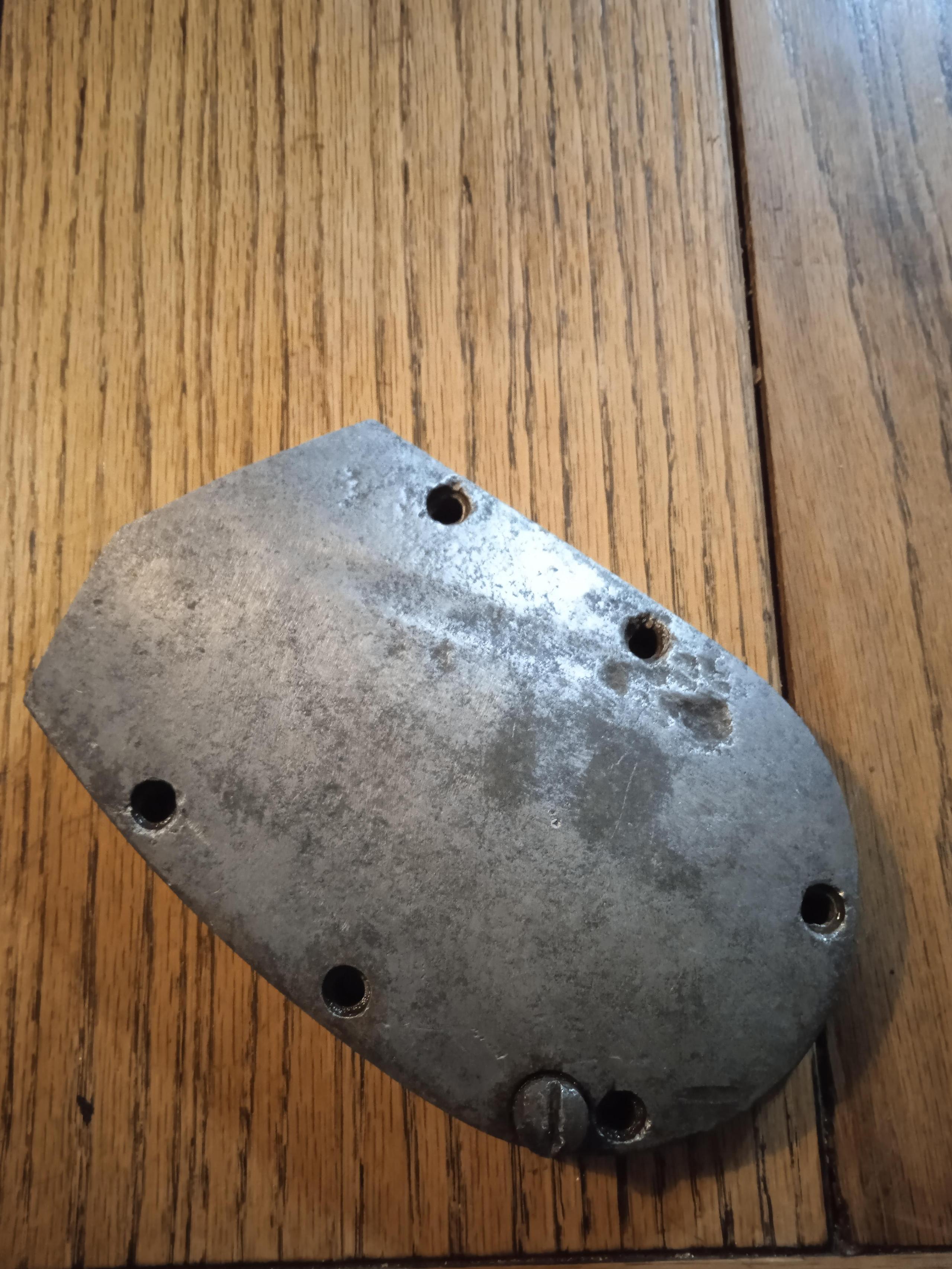
application. I have altered a spare M20 brake plate, (picture 3), to
evaluate this modification, and also added the internally threaded
sleeve for the right side speed drive.
BM
10/24
Front Brake modifications
Ignition timing tools
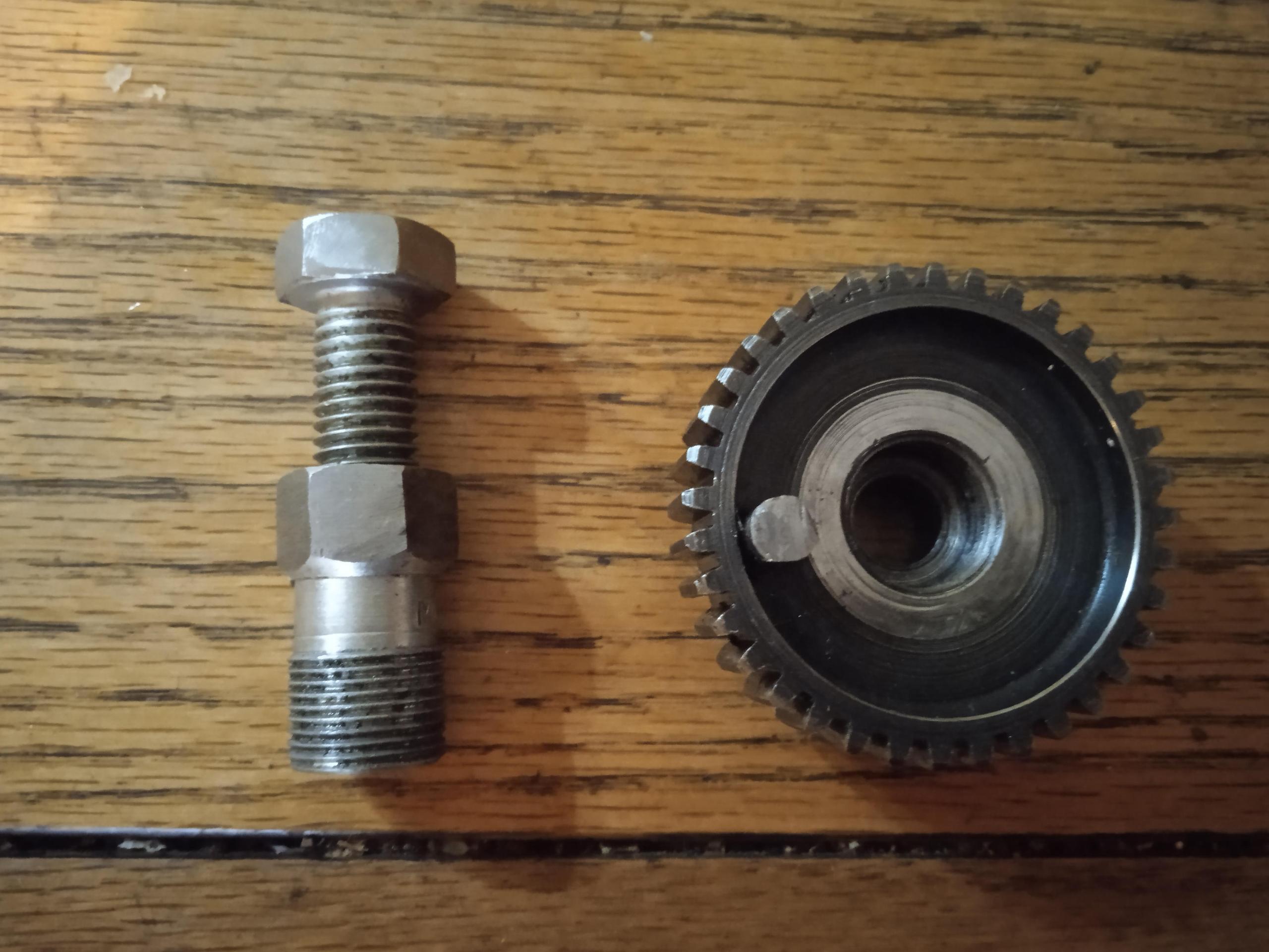
From left - 1) Rod marked for TDC and 7/16 inch BTDC. 2) Degree disc with pointer wire. 3) TDC position finder made from a piece of threaded bar, two nuts, and a used 14mm spark plug with the ceramic insulator removed. The engine is turned until finder touches top of the piston before, and after, TDC. Half way in between, as indicated on the degree disc, is TDC
16) BSA Service sheets (can be downloaded from internet)
BSA Service sheets (relevant to M24 Gold Star)
Number |
year |
Subject |
63d |
1938 |
Piston rings |
63e |
1938 |
Warning piston rings 37-1938 |
82 |
1938 |
B&M Group machines, oil in primary chaincase |
84 |
1938 |
Cylinder liners |
86 |
1938 |
Cylinder liners and pistons |
93 |
1938 |
Gear ratios |
94 |
1938 |
Home Carburettor settings 1939 |
91 |
1938 |
Sparking plugs (KLG 831) |
92 |
1939 |
Ignition timing |
133 |
1937- 8 |
Conrod and Bigend |
304 |
|
Engine complete dismantling (B) |
305 |
|
Reassembling engine (B) |
308 |
|
Clutch |
539 |
1938 |
Carburettor settings |
540 |
1938 |
Sparking plugs |
541 |
1938 |
Ignition timing |
542 |
1938 |
Gear ratios |
602 |
|
Gearbox exploded view |
603 |
|
Lubrication system (B,C&M |
604 |
|
Engine adjustments (B&M) |
606 |
|
Removing engine from frame and complete dismantling |
607 |
|
Reassemnling the engine |
608 |
|
Gearbox and gearchange |
609 |
|
Transmission |
611-612 |
|
Brakes and Hubs relining |
613 |
|
Adjustments to Steering head and forks |
514- 706 |
|
Front Forks |
701 |
|
All models useful data |
702 |
|
workshop data (bushes) |
703 |
|
Workshop data bearings |
704 |
|
Piston clearances |
705 |
|
Periodic attentions |
709 |
|
Fault finding |
710 |
|
Chain alteration and repair |
731 |
1938-52 |
Service tools |
802 |
|
Ignition system Magdyno |
804 |
|
Voltage Regulator unit |
805 |
|
Battery |
806 |
|
Lamps |
807 |
|
Electric horn |
808 |
|
Electrical wiring system - earth |
808A |
|
Wiring diagram + earth |
|
|
Rigid frame B&M adjustment, dismantling and re-assembly of the rear hub and brake |
